GATEWAY INSTALLATION MANUAL
Here you’ll find the manual needed to setup the SenArch Arch I gateway
You can download the manual here as PDF
Please make sure to read the entire manual before installing the Arch I

If you are on a mobile device you can refer to the individual quick guides in the fans below
Quick guides
Do only refer to these quick guides once the full product manual has been read
Tap the bars to unfold the chapter
Guide to removing battery strip from gateway
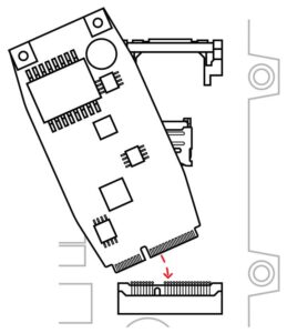
Main board battery strip removal
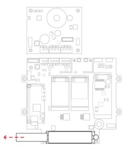
Open the gateway enclosure using a Phillips screwdriver
Locate the Li-ion battery on the main board inside the gateway enclosure
Pull out the battery strip as illustrated
Guide to replacing the SIM card
SIM card installation
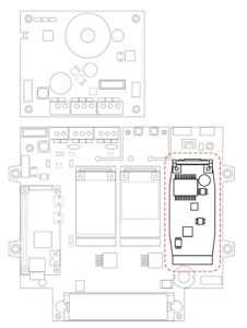
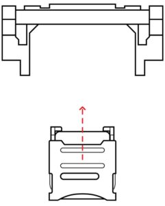
1. Locate the co-host board inside of the gateway enclosure
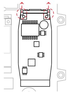
2. Pull the two lock pins up to release the top of the co-host board
3. Put the co-host board aside in a non static location to reveal the SIM card slot
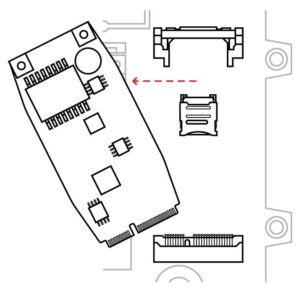
4. push the SIM card slot shield upwards to unlock and open it
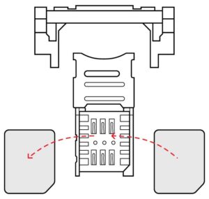
5. Insert or exchange the SIM card
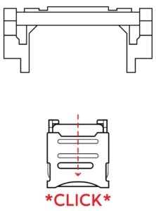
6. Close the shield and lock it by pushing it downwards until it clicks
7. Reinsert the co-host board into the bottom slot
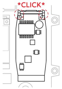
8. Click the top of the co-host board back into the lock
Pole mounting guide
Solar panel clearance and orientation
![]()
When attaching the solar panel, make sure the bottom of the solar panel frame is cleared by at least 5 cm over any obstacle
Make sure the solar panel is unobstructed for as many hours a day as possible

If gateway is placed on the northern hemisphere, point the solar panel towards south
If gateway is placed on the southern hemisphere, point the solar panel towards north
Battery cabinet installation
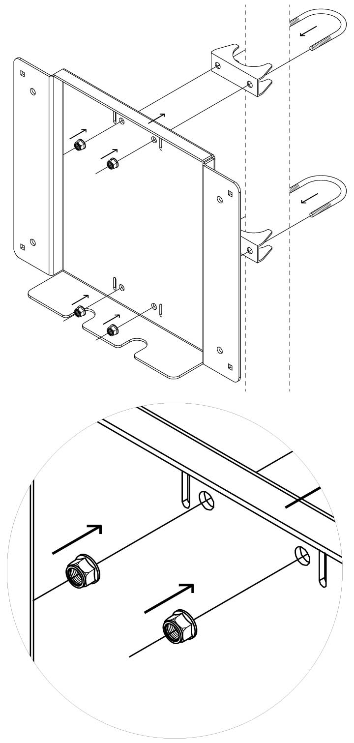
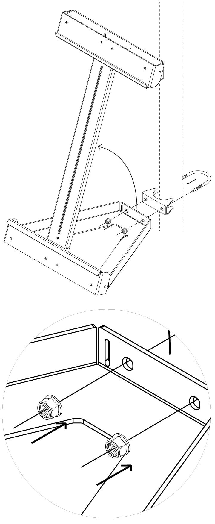
1. Attach the battery enclosure mounting plate to the pole, using the U-bolts, U-bolt brackets and the M8 self-locking nuts as illustrated
2. Place the battery cabinet onto the mounting plate rest so that the holes on the mounting plate and the back of the cabinet line up
3. Insert the M6 round head bolts into the outer most corner holes in the mounting plate so that they enter the battery enclosure
4. On the inside of the battery enclosure, fasten the M6 round head bolts with M6 self-locking nust as illustrated.
Push in on the door while turning the key for easier opening and closing of the enclosure
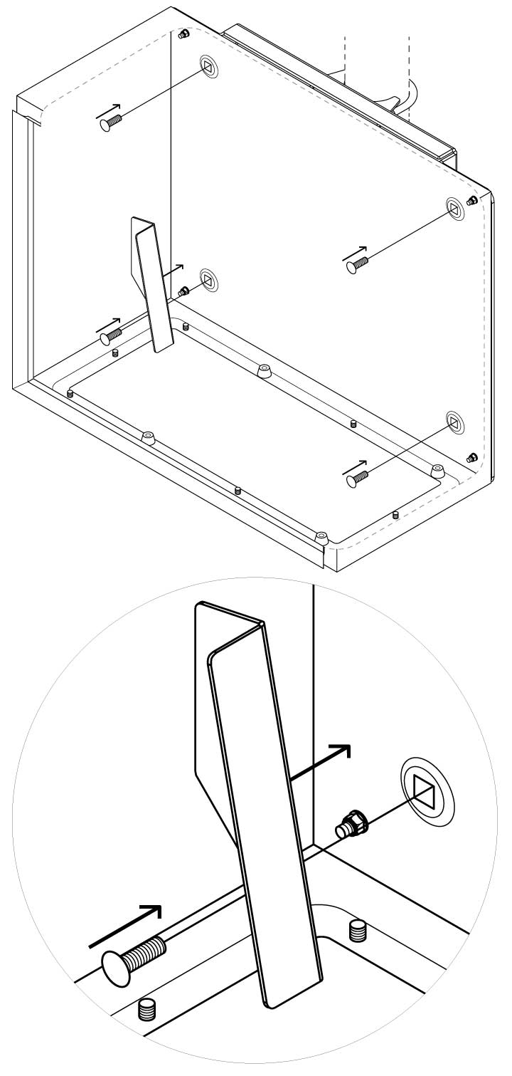
5. Place the battery slider in the bottom left corner inside the battery enclosure as illustrated.
Insert the M8 round head bolts into the inner most holes inside the battery enclosure so that they go through the mounting plate

6. Fasten the M8 round head bolts with each a M8 nut for battery enclosure on the back of the mounting plate as illustrated
Solar panel installation
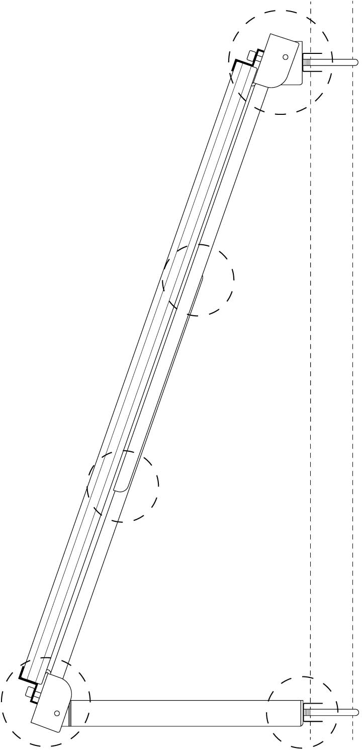
1. Lift up the solar panel frame arm and fasten the bottom to the pole, using a U-bolt, U-bolt bracket and two M8 self-locking nuts. Fasten tightly.
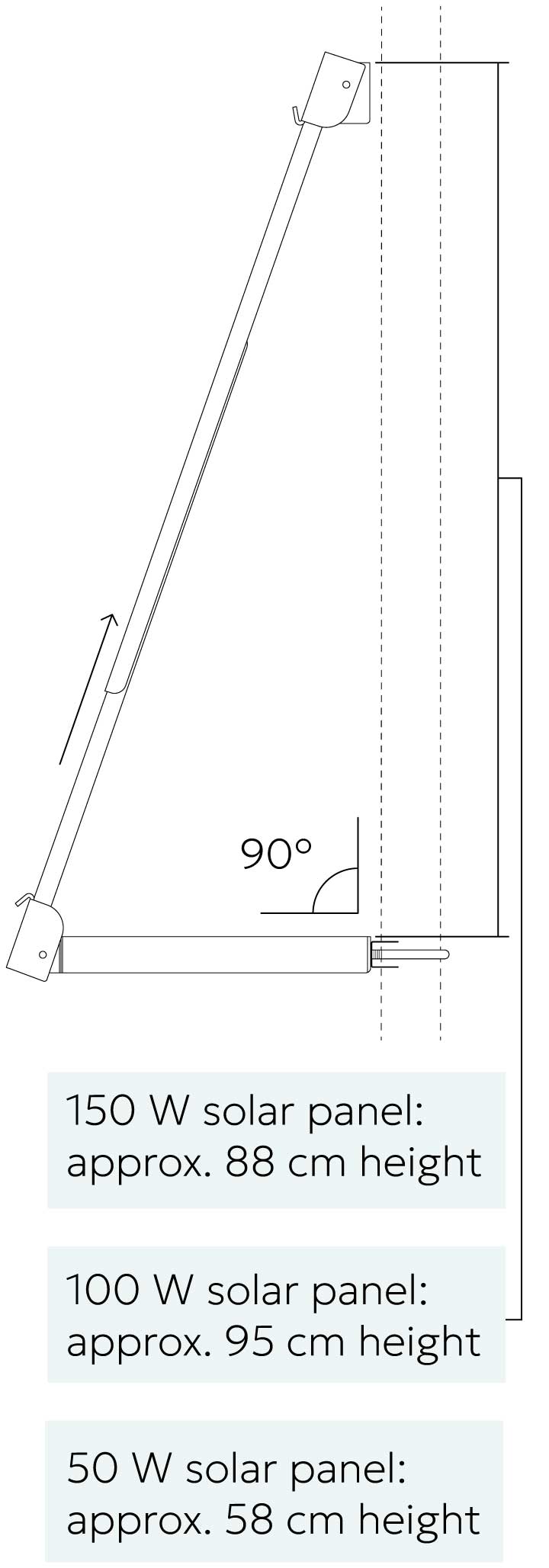
2. Extend the arm according to the solar panel used.
Make sure the bottom plate of the frame is
fastened to the pole at a 90 degree angle.
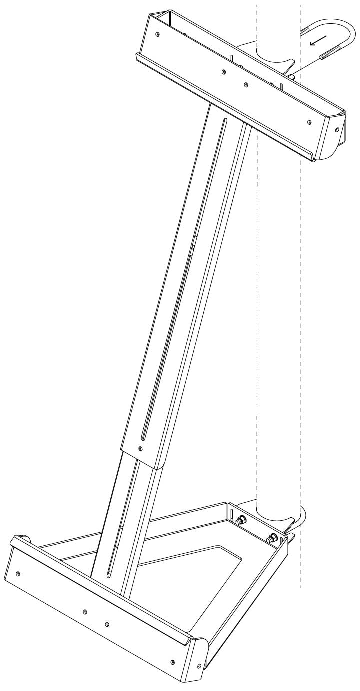
3. Fasten the top of the frame to the pole using the same method as step 1. Fasten tightly.
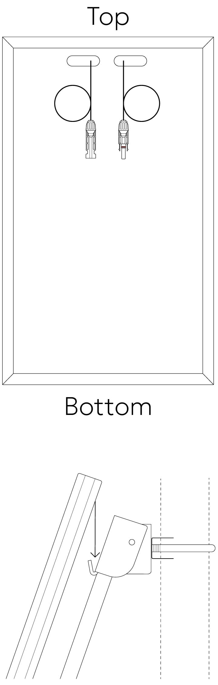
4. Lower the top of the solar panel down onto the hook ledge so that the solar panel is hanging safely.
The top of the solar panel needs to be the end with the wires.
Make sure the solar panel is centered with the pole.
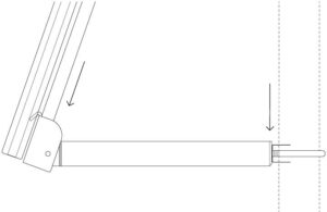
5. Loosen the the bottom U-bolt so that the bottom of the frame can be extended downwards.
Extend until the hook ledge is locking the bottom edge of the solar panel.
Tighten the U-bolt tightly again.
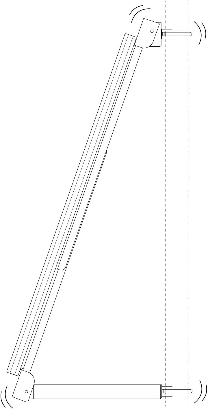
6. Test if the solar panel frame is securely fastened to the pole and that the solar panel cannot be moved vertically. You shold not be able to move the solar panel frame out of place.
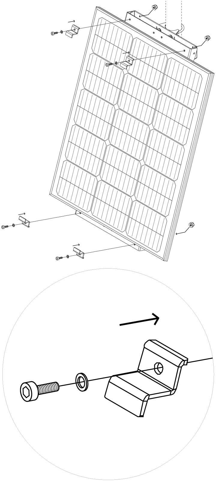
7. Screw on the solar panel mounting brackets as illustrated using the socket head cap screws, washers and self-locking nuts to secure the solar panel to the solar panel frame
8. Finish solar frame installation by tightening all screws on the frame.
Antenna installation

1. Unscrew and put aside the bolt and washer from the bottom of the antenna
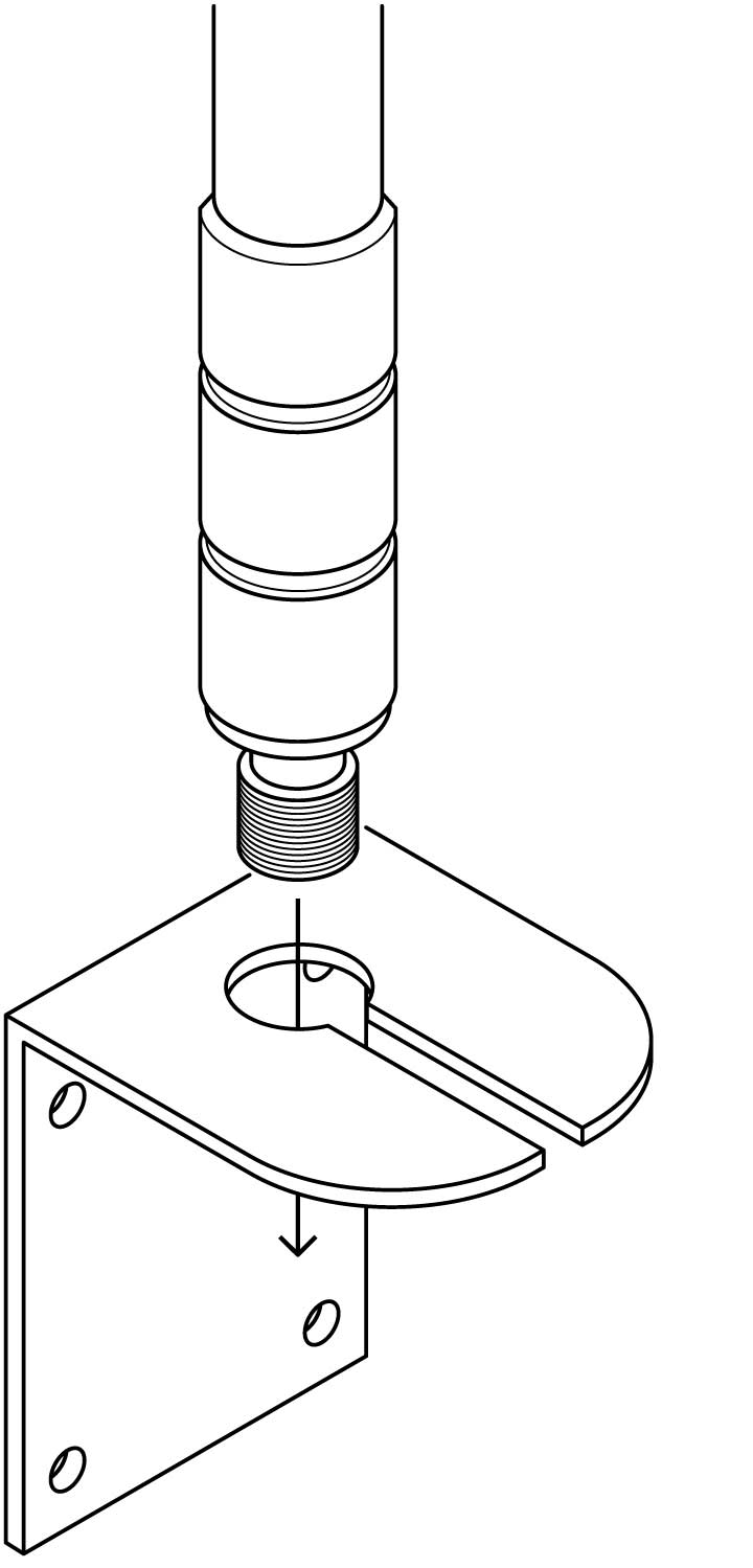
2. Place the bottom of the antenna into the hole in the mounting bracket
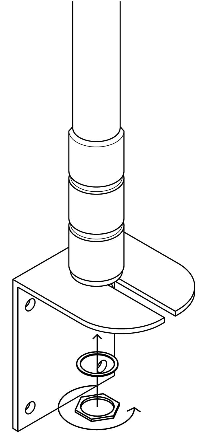
3. Fasten the antenna to the mounting bracket with the washer and bolt put aside in step 1.
Make sure it is fastened tightly
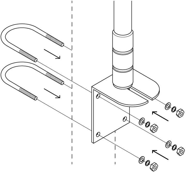
4. Attach the mounting bracket with the antenna to the pole, using the U-bolts, washers, lock-washers and bolts as illustrated
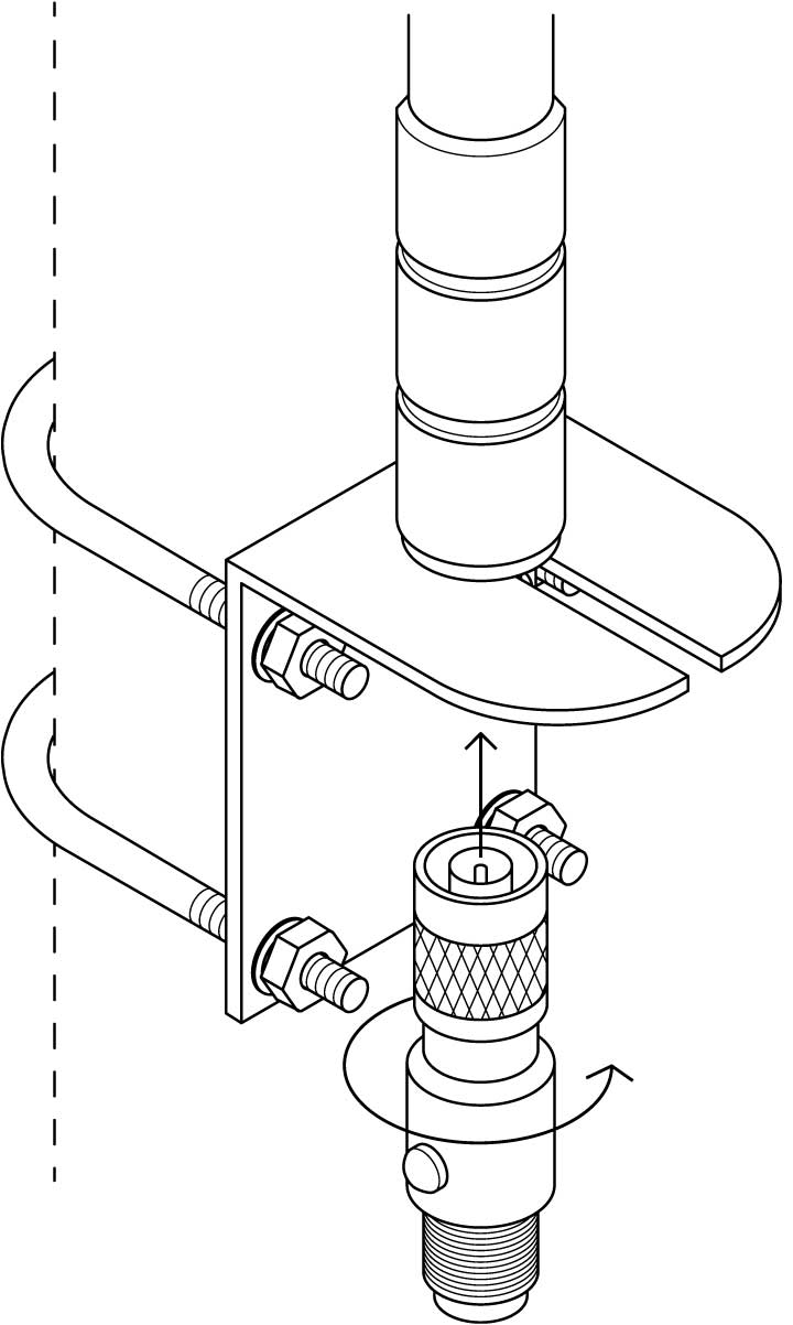
5. Tightly screw in the lightning arrester to the bottom of the antenna
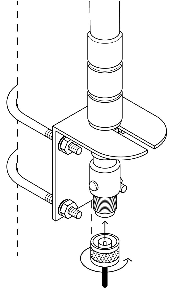
6. Tightly screw in the N-type coaxial cable to the bottom of the lightning arrester
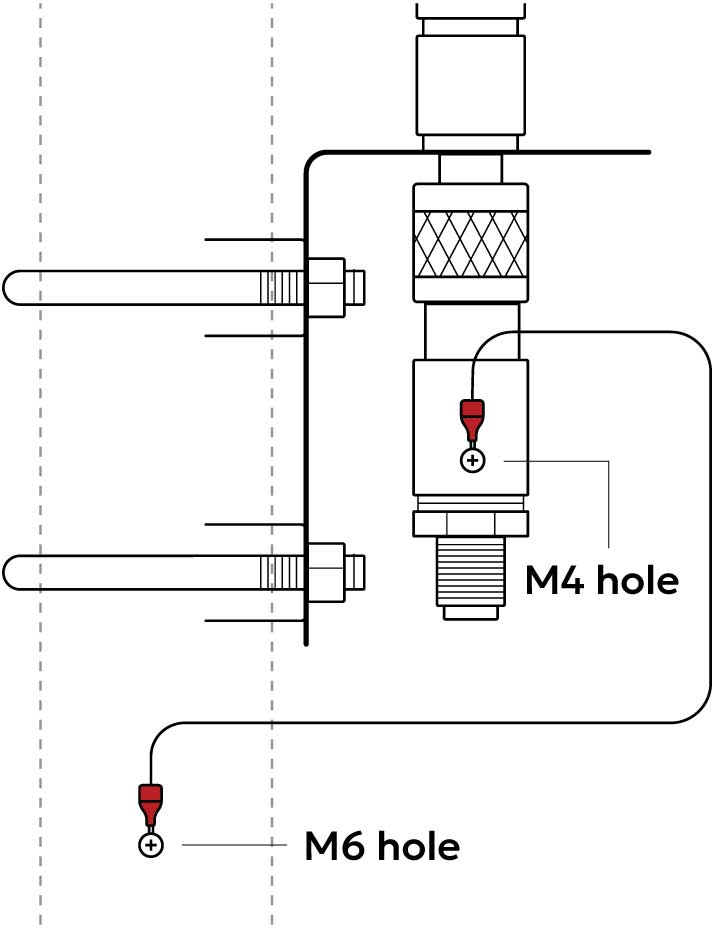
7. For safety, screw the M4 end of the ground plane wire to the lightning arrester on the antennas and the M6 end to a metal surface, for example the mounting pole

8. We strongly recommend wrapping the lightning arrestor in vulcanising tape for weather protection.
Vulcanising tape not included
Gateway enclosure installation
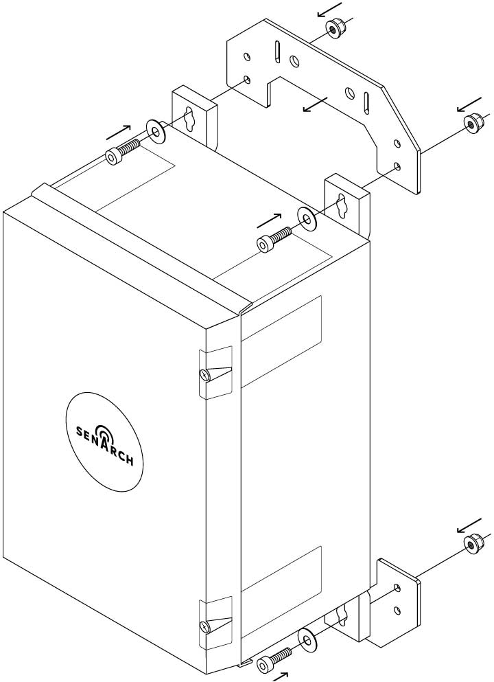
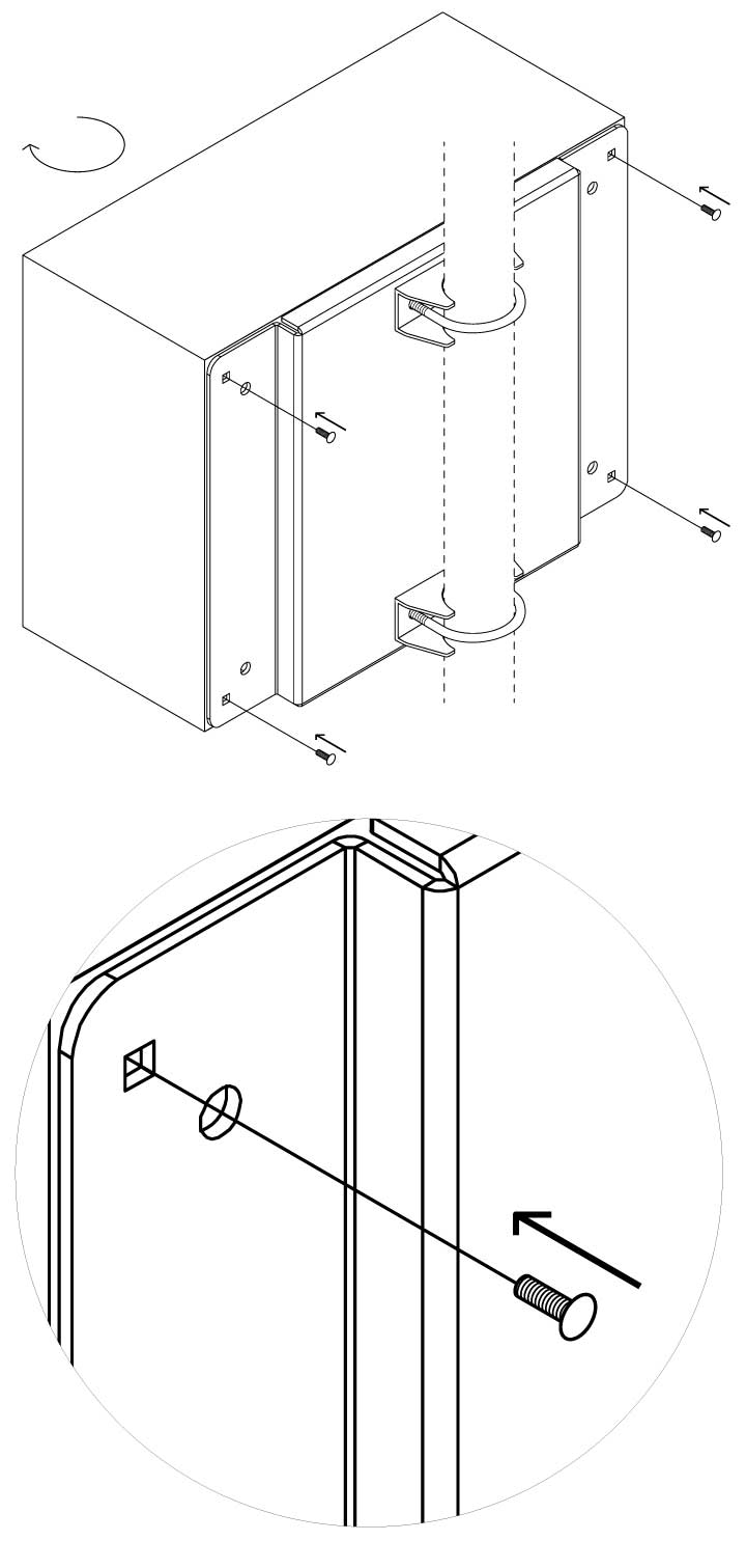
1. To prepare the gateway enclosure for mounting, screw on the gateway enclosure mounting brackets using the socket head cap screws, big washers, small washers and self-locking nuts as illustrated.
It is recommended to do this step right out of the box
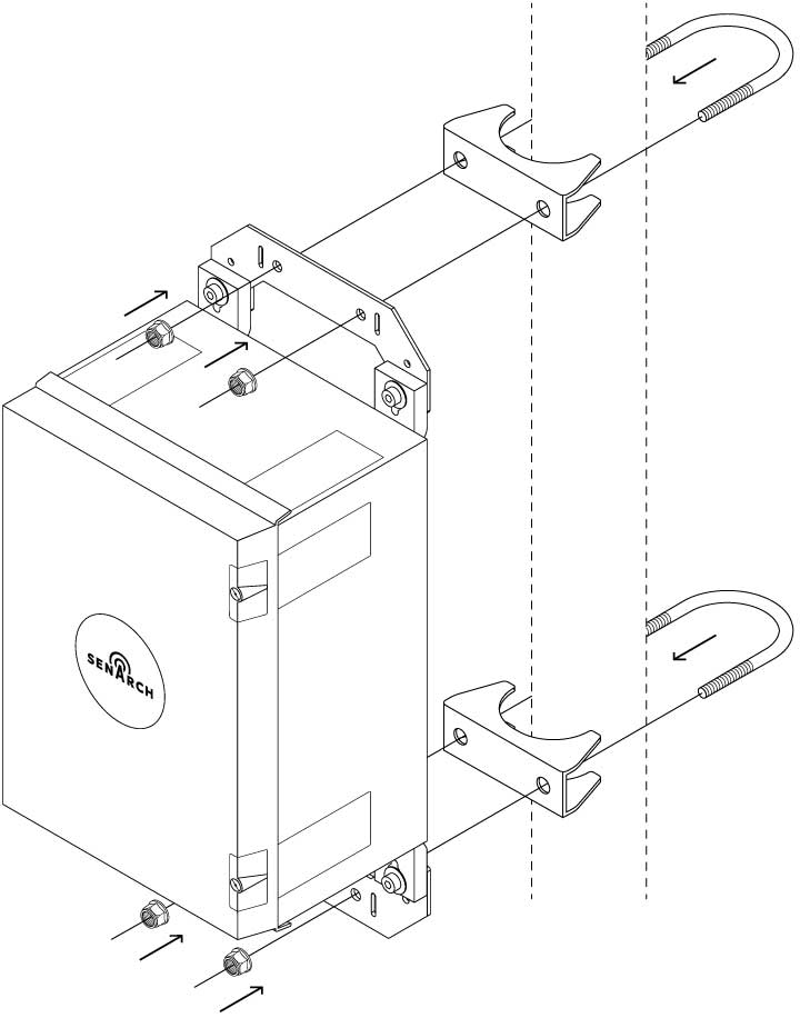
2. Attach the gateway enclosure mounting
brackets to the pole, using the U-bolts, U-bolt brackets and the M8 self-locking nuts as illustrated
It is recommended to install the gateway
enclosure behind the solar panel mount
Mounting with metal bands
It is possible to fasten the gateway enclosure, solar panel frame and battery enclosure to a pole using bands instead of u-bolts.
This works as illustrated:
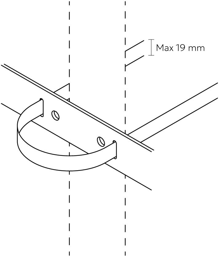
Use any kind of high strength and durability fastening band.
Fastening band can have a max width of 19mm
Tightening the band is dependent on the type of band used. Refer to the instructions of the type of band used
Fastening bands not included
Recommended: Band-It bands
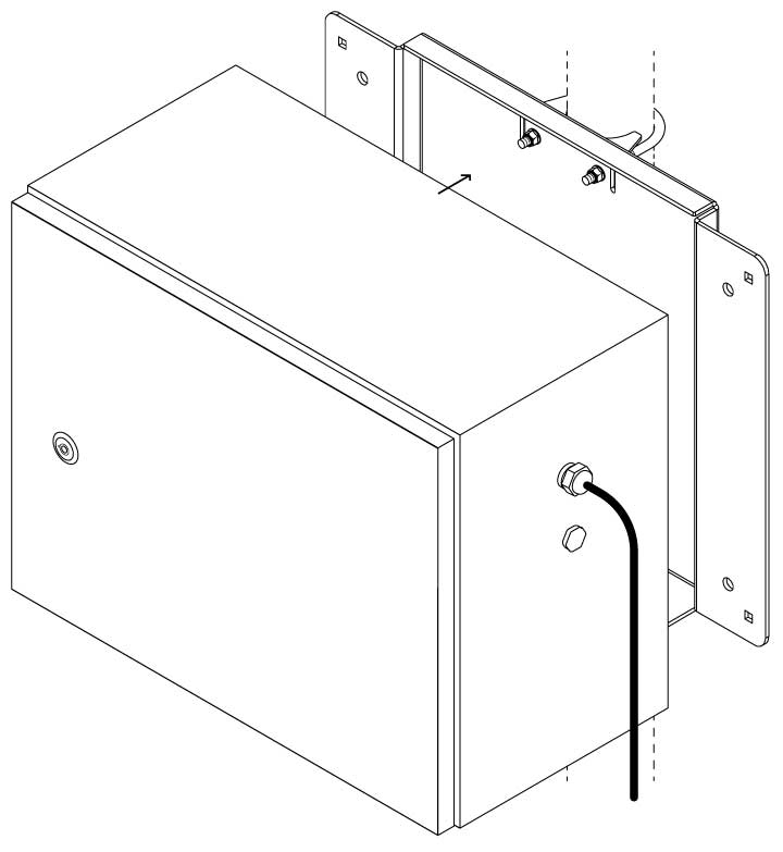
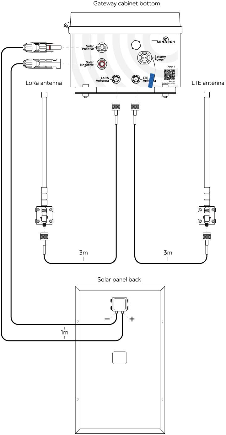
Cable connections
Connect the cables of the LoRa antenna, LTE antenna and solar panel into the gateway as illustrated
Do not connect the battery power yet!
Powering up the system
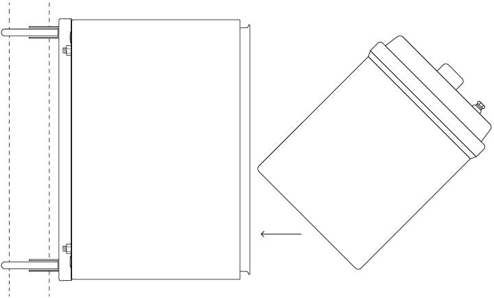
1. Tilt the battery towards yourself with the terminal side of the battery closest to you
Be careful to not touch the battery
terminals while handling the battery
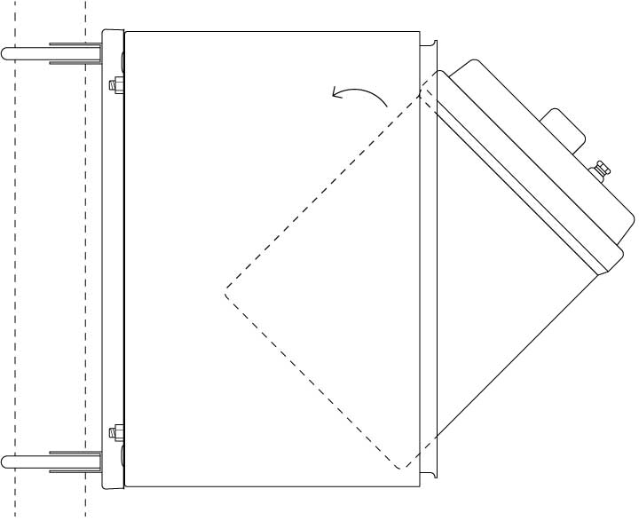
2. Lift the battery into the battery enclosure so that the bottom corner closest to you is resting just
inside the enclosure. Then let the battery fall into an upright position. The battery slider will make sure the battery is positioned correctly
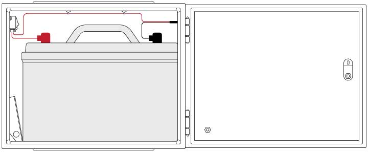
3. Connect the eye connectors in the battery
enclosure to the correct terminals on the battery and cover them with the rubber hoods
CAUTION
it is critical that the
positive connector (red wire)
is connected to the positive
terminal (red)
The negative connector (black wire)
has to be connected to the
negative terminal (black)
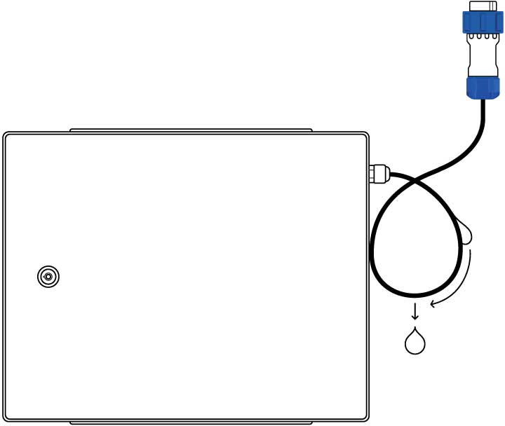
4. As a safeguard, make a downwards loop with the battery cable and lock it with a tie wrap to direct the rain water away preventing it from entering into the
enclosure through the port.
See illustration.
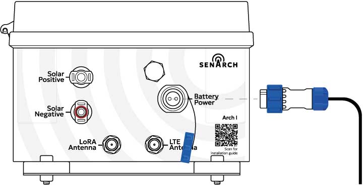
5. Plug in the battery cabinet to the gateway
enclosure as illustrated
The gateway is now powered on 🙂
SenArch tripod mounting guide
Tripod mounting and securing
When installing the Arch I on the SenArch optional tripod, refer to the pole mounting instructions
It is recommended to install the gateway on the tripod in the order and setup illustrated here:
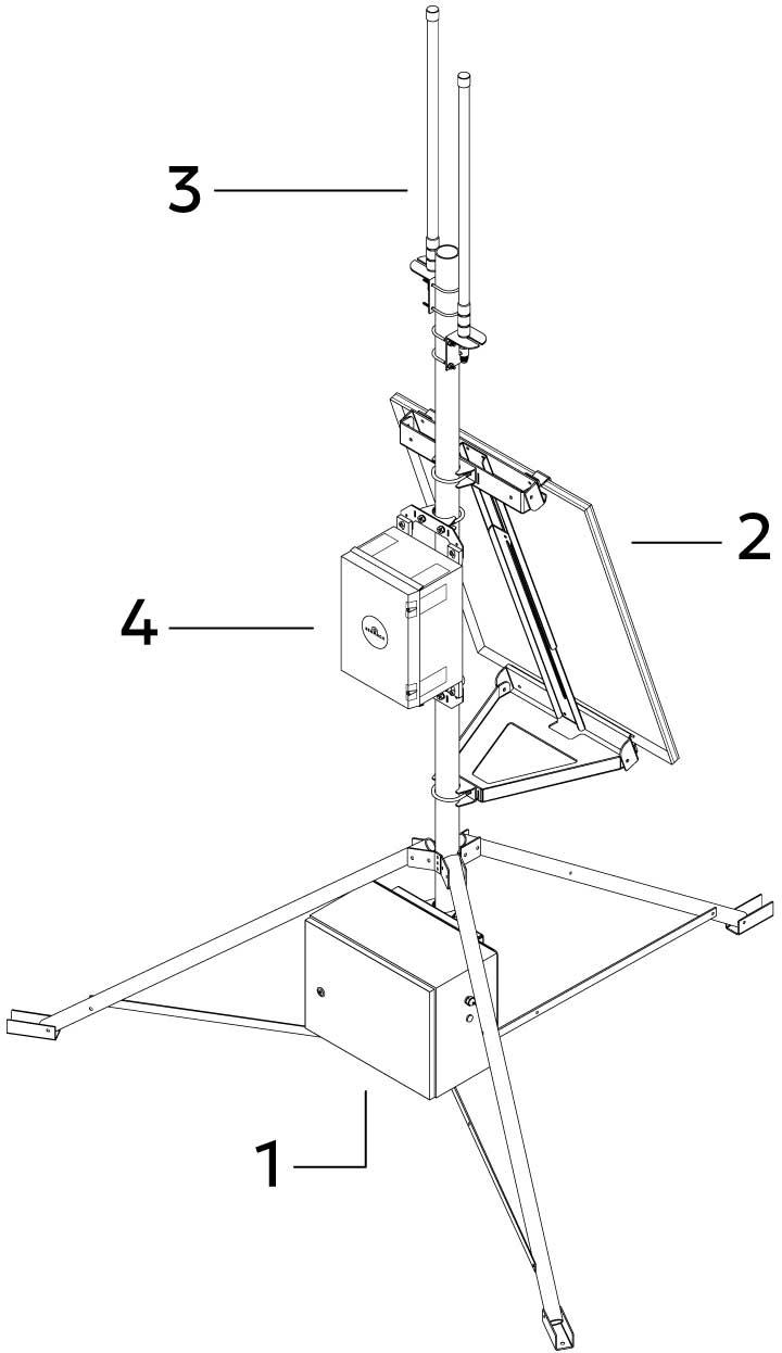
1 – Battery enclosure
Centered in between two legs
of the tripod
2 – Solar panel
Straight above a leg of the tripod on the opposite side of the battery enclosure
3 – LoRa & LTE antennas
One antenna on either side of the tripod pole, one above the other
4 – Gateway enclosure
Directly above the battery enclosure and in the space behind the solar panel
When setting up the SenArch tripod it is important to secure it to the ground to prevent it tipping over and damaging the gateway or preventing the gateway from functioning.
Securing the tripod can be done in any way fitting for the deployment setting and does not have to follow a ruleset.
However, we recommend securing the tripod in one of the following ways:
Bolted to tiles (for hard surfaces):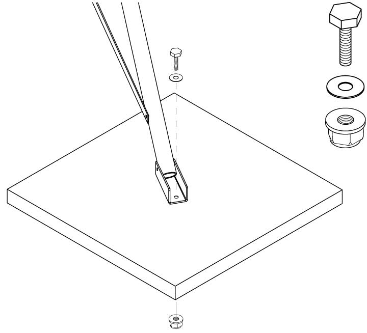
Bolt each foot of the tripod by drilling a hole through a heavy pavement tile and fastening with a bolt with a fitting washer and a self locking nut. The bolt can not exceed a diameter of 10 mm
Pegs (for deployment on soil surface):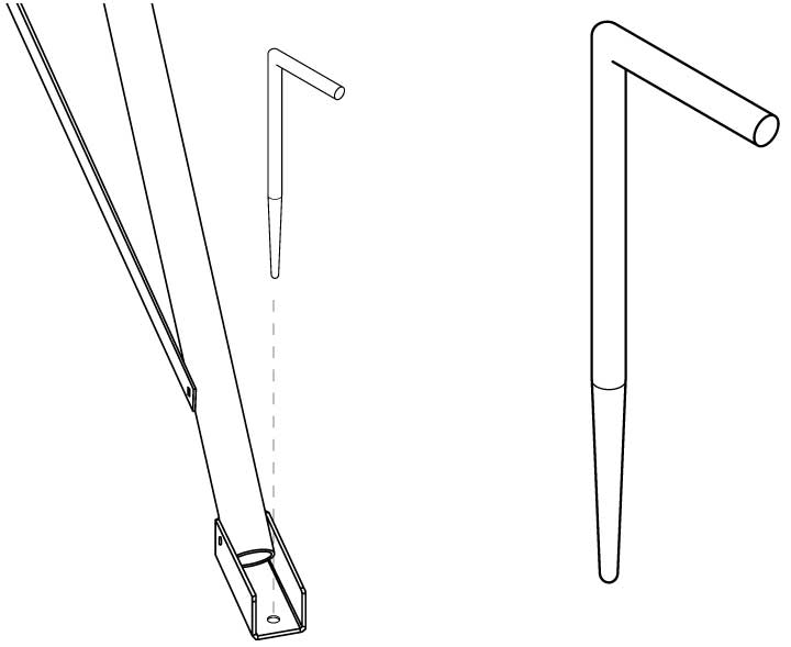
Use any type of long and strong peg to secure each foot of the tripod to the ground.
The diameter of the peg should optimally be 10 mm
Parts for securing the tripod are not included
Wall mounting example
Wall mounting
Wall mounting is an optional method of installing the Arch I.
When installing the Arch I on a wall, refer to the pole mounting instructions, for the steps beyond wall mounting.
This chapter is only an example and not a step by step guide
Depending on the type of wall to which the Arch I is installed, other methods or tools might be needed.
Research the best way of fastening equipment to the type of wall in
question before starting the wall
mounting process.
Example of wall mounting bolts and nuts:

Carbon steel expansion bolts M8 (M6 for antennas) (not included)
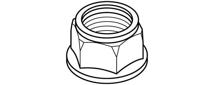
Self locking nuts M8
Installing the wall mounting bolts:
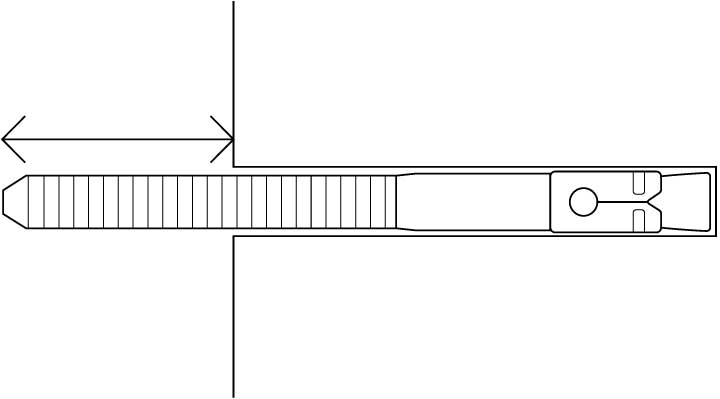
Refer to the installation instructions of the bolt you have acquired on how to install them into your surface.
Check the following diagrams for the maximum extrusion the bolt can have from the wall
Bolt measurements for each module:
On these diagrams you can see the distance needed between the wall bolts, and the maximum allowed extrusion of the bolt from the wall, for each module of the Arch I.
It is recommended that you measure these distances yourself before starting the wall mounting installation to lower the chances of errors.
Gateway enclosure: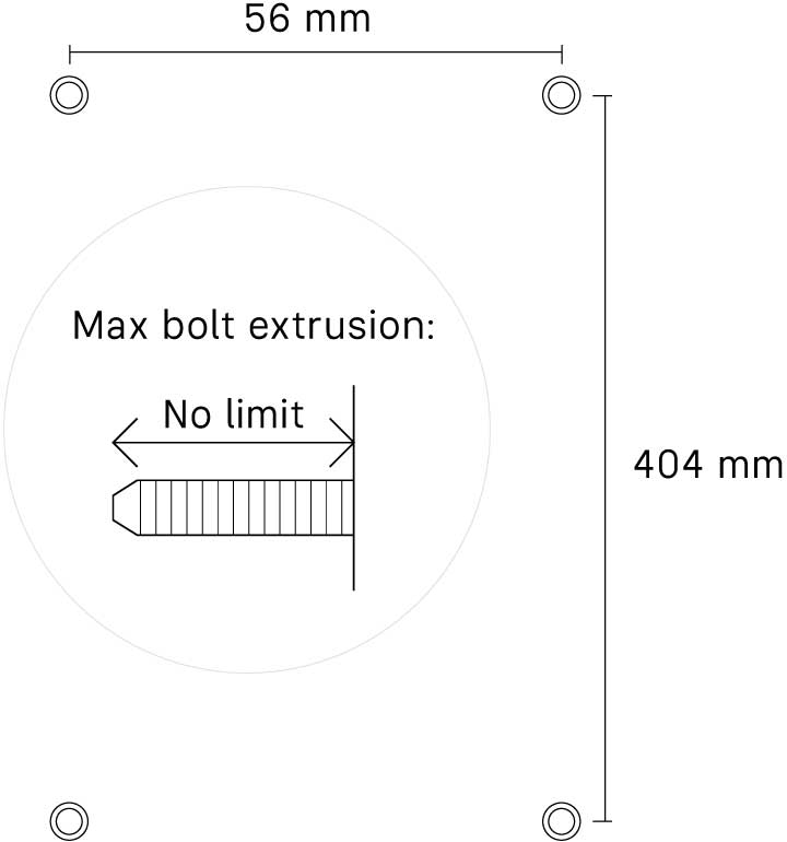
Antennas: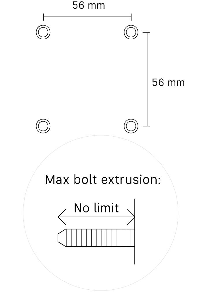
Solar panel frame: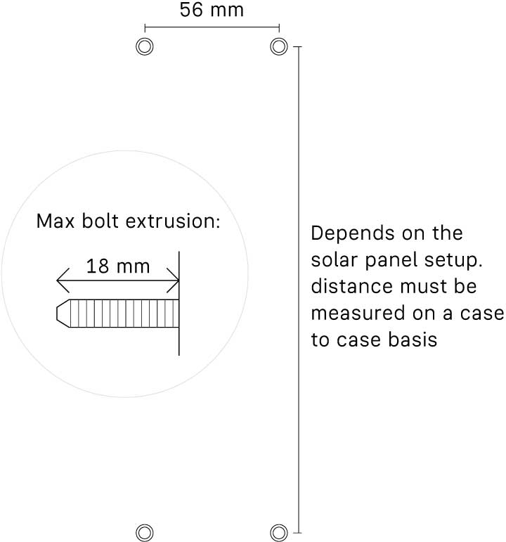
Battery back plate: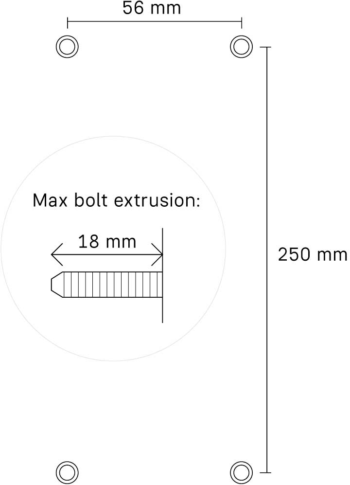
Installing on wall:
Solar panel frame: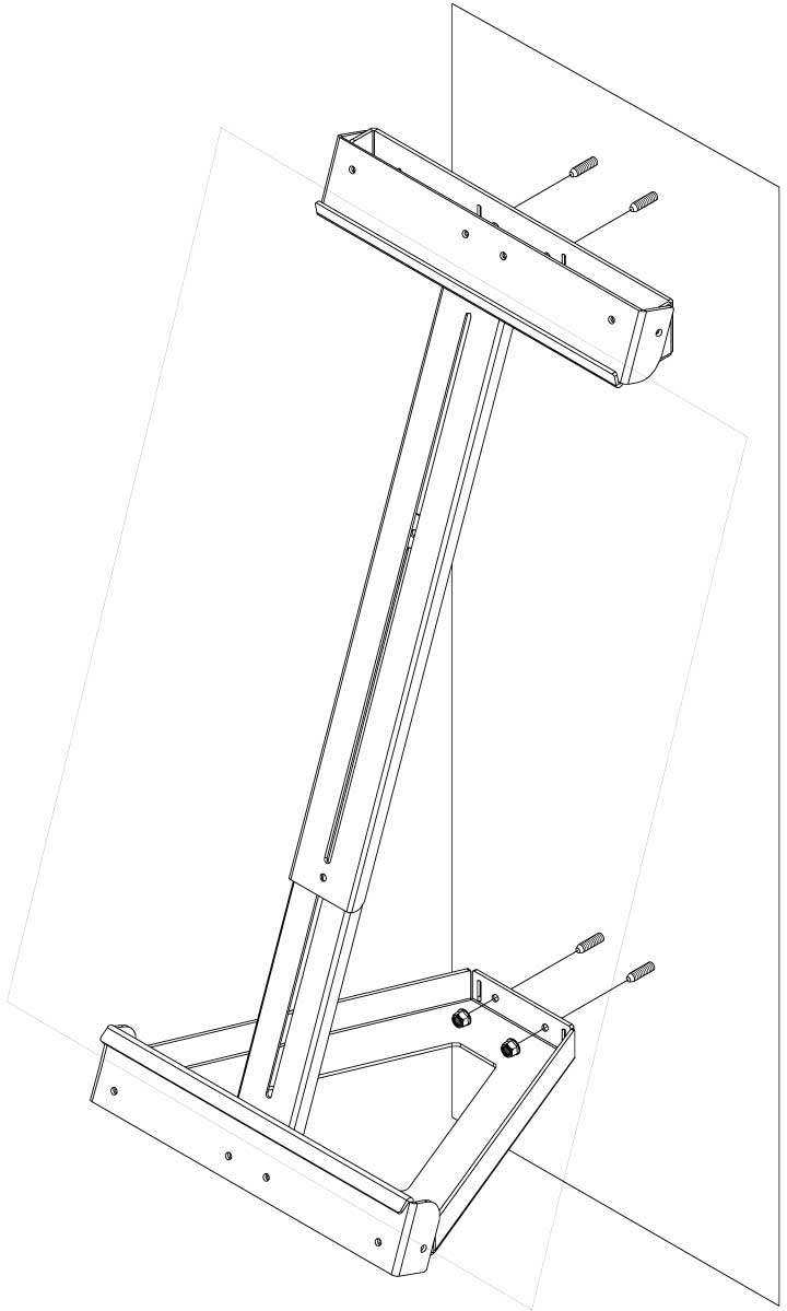
You can fasten the solar panel frame to the wall using M8 self locking nuts onto M8 Expansion bolts in the wall.
Install the solar panel onto the solar panel frame before starting the wall mounting process to make sure you have the correct measurements
Antennas:
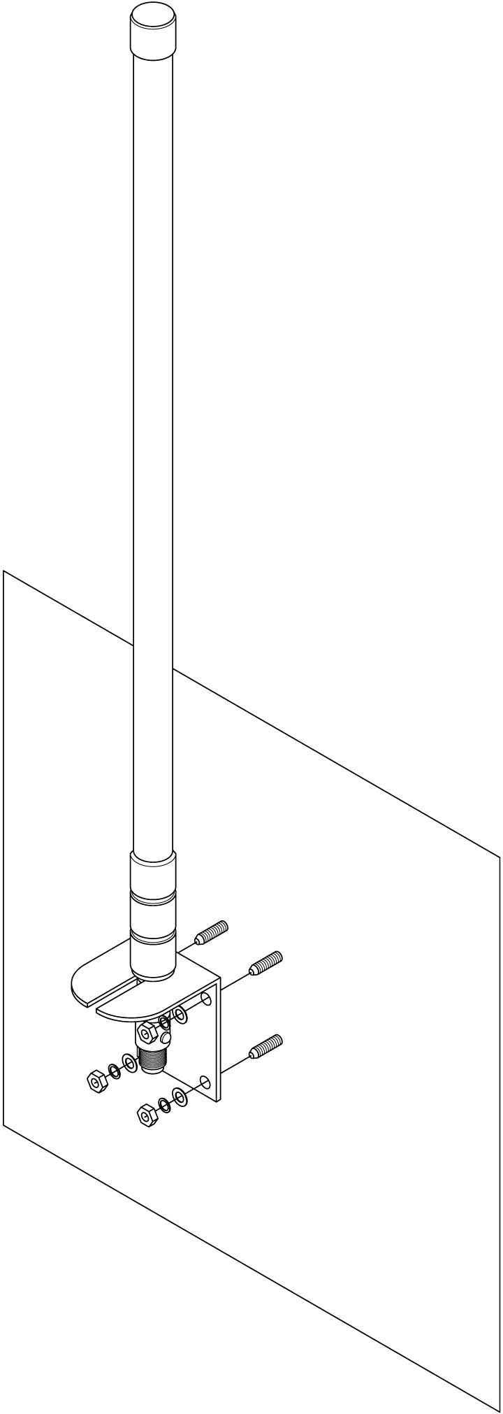
You can fasten the solar panel frame to the wall using the nuts and washers included onto M6 Expansion bolts in the wall.
Alternatively a short pole (max 48mm width) can be attached to the wall on which the antennas can be installed with U-bolts.
To prevent loss of efficiency do not install the antennas too close to any metal plating.
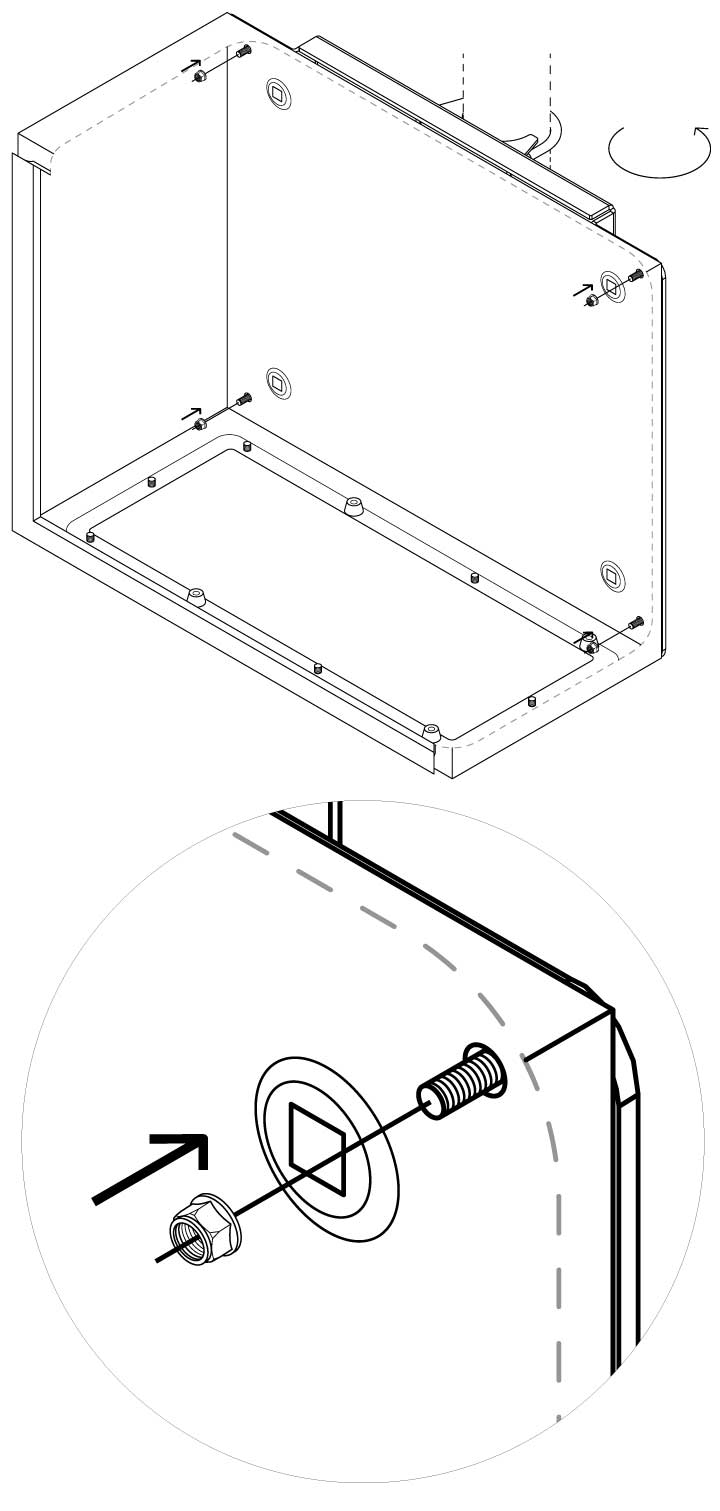
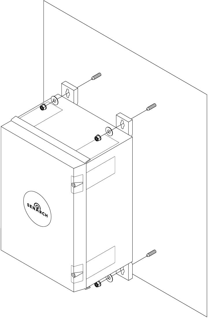
Battery back plate: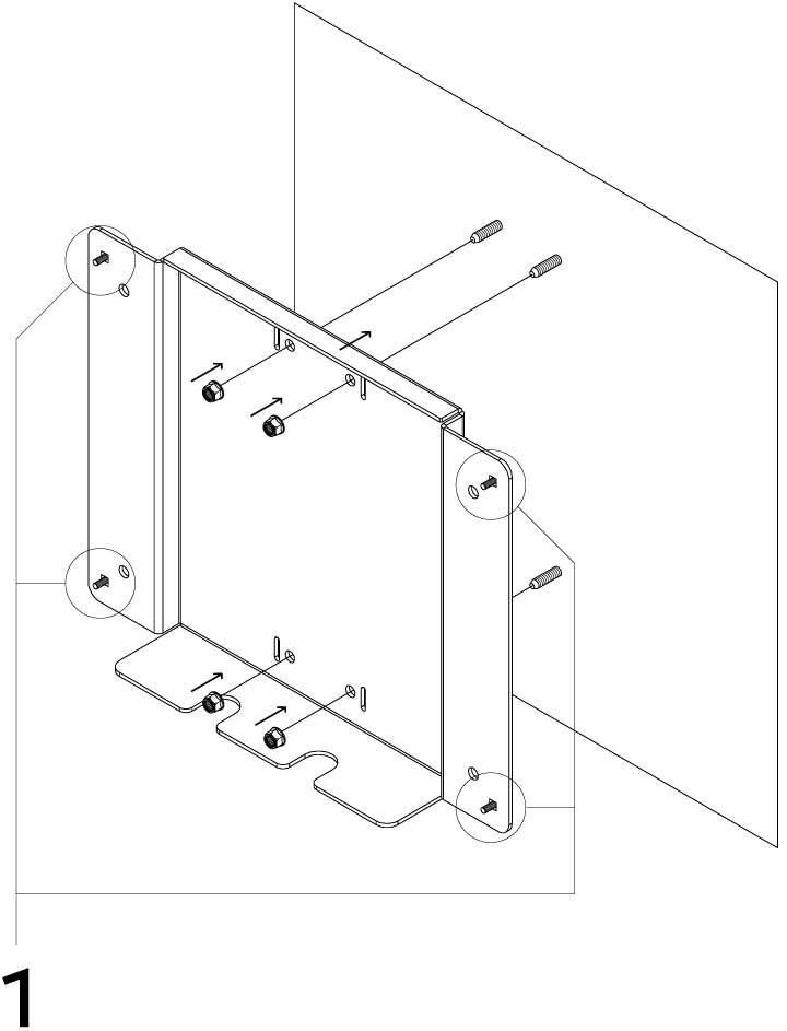
You can fasten the solar panel frame to the wall using M8 self locking nuts onto M8 Expansion bolts in the wall
1 – Before putting the back plate on the wall, make sure to insert the M6 round head bolts into the outer most corner holes in the mounting plate as illustrated
Continue installing the battery enclosure by following the steps in the “powering up the system” instructions.
Gateway enclosure:
You can attach the gateway enclosure directly on the wall without the included mounting brackets, using M8 self locking nuts onto M8 Expansion bolts in the wall.
Depending on how far apart the gateway parts are installed, extension cables may be needed